


SPD AC Power Surge Protector
Basic Info
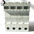
Model No.: DS2-40/4
Product Description
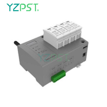
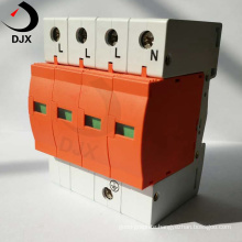
 SPD Power Surge/Lightning Protection Device Surge/Lightning Arrester Product Description 1.Application It is installed in the low voltage power circuit as class I, classII and class III lightning and surge protection. 2.Service Environment Temperature:-40℃~+80℃ Humidity:≤90% ( average 25℃) Non-flammable and non-explosive environment Protect against light, rain etc.. 3. Instructions for Use DS2-40/4 4pcs/group, installed in TN-S and TN-C-S, used for three-phase power lightning protection. DS2-40/3+NPE 4pcs/group, installed in TT, used for three-phase power lightning protection. DS2-40/3 3pcs/group, installed in TN-C and IT, used for three-phase power lightning protection. DS2-40/2 2pcs/group,installed in TN-S and TN-C-S,used for single phase power lightning protection. DS2-40/1+NPE 2pcs/group, installed in TT, used for single phase power lightning protection. DS2-40/1 single pc module, used for single phase power lightning protection.


 Specifications
 | Model | DS3-20 | DS3-20 | DS2-40 | DS2-40 | DS1-60 | DS1-80 | DS1-100 | |
Max. Continuous Operating Voltage | Uc | 385∼ | 385∼ | 385∼ | 385∼ | 385∼ | 385∼ | 385∼ |
Nominal Discharge Current (8/20µs) | In | 10kA | 10kA | 20kA | 40kA | 30kA | 40kA | 60kA |
Max. Discharge Current (8/20µs) | Imax | 20kA | 20kA | 40kA | 40kA | 60kA | 80kA | 100kA |
Voltage Protection Level at In | Up | ≤1.2KV | ≤1.5KV | ≤1.5KV | ≤1.8KV | ≤2.0KV | ≤2.3KV | ≤2.5KV |
Front Fuse | 63A | |||||||
Response Time | tA | ≤25ns | ||||||
Indicator | Green for Normal/ Red for Fault | |||||||
Maintenance Function | Pluggable | |||||||
Remote Signal Connection Point | 11,13 normal close,12,13 normal open | |||||||
Wiring Method | Parallel | |||||||
Operating Temperature | -40℃~+80℃ | |||||||
Wire Cross-section | 2.5mm2 ~25mm2 | |||||||
Wire Cross-section of Remote Signal Port | 0.5mm2 ~1.5mm2 | |||||||
Shell Material | Flame retardant plastic | |||||||
Protection Grade of the Shell | IP20 | |||||||
Size | One switch position(width 18mm) | |||||||
Installation Frame | 35mm Din Rail | |||||||
 Installation SPD Installation Instructions Close to the power switch or the device to be protected; Parallel connection to the power circuit; Connection wire should be cooper wire not less than 6mm2 , and it should be short, thick and straight; It is better to use V type connection; Be mounted on 35mm Din rail; If power fuse F1 is more than 63A, it is necessary to install fuse F2 63A before the SPD; Remote signal connection port 11,13 should be connected to the indicator circuit to show normal and fault, or remote signal connection port 12, 13 be connected to loudspeaker circuit for fault warning.
  Contact us if you need more details on spd. We are ready to answer your questions on packaging, logistics, certification or any other aspects about Surge Protector、ac surge protector. If these products fail to match your need, please contact us and we would like to provide relevant information.
 Product Categories : SPD Surge Protector
Premium Related Products
Other Products


Hot Products
Flexible Graphite Sheet Production LineFlexible Graphite Sheet Machine1.0 Meter Graphite Sheet rolling millGraphite Paper Coiling MachineFlexible Graphite Conduction FilmThermal Conductive Graphite PaperComputer Graphite Conduction FilmHigh Quality Flexible Graphite CoilHigh Quality Graphite StuffingHigh Quality Flexible Graphite GasketingNatural Flake Graphite PowderUltra-thin Thermal Conductive Graphite FilmHigh-purity Flexible GraphiteHigh Quality Graphite Braided PackingSprint Graphite Reinforced Composite PanelGraphite Plating Composite Panel